Depending on the system earthing arrangement, the maximum continuous operating voltage Uc of SPD must be equal to or greater than the values shown in the table in Figure 1.
Fig.1 – Stipulated minimum value of Uc for SPDs depending on the system earthing arrangement (based on Table 534.2 of the IEC 60364-5-53 standard)
SPDs connected between (as applicable)
System configuration of distribution network
TN system
TT system
IT system
Line conductor and neutral conductor
1.1 U / √3
1.1 U / √3
1.1 U / √3
Line conductor and PE conductor
1.1 U / √3
1.1 U / √3
1.1 U
Line conductor and PEN conductor
1.1 U / √3
N/A
N/A
Neutral conductor and PE conductor
U / √3
U / √3
1.1 U / √3
Attn: N/A: not applicable
U: line-to-line voltage of the low-voltage system
The most common values of Uc chosen according to the system earthing arrangement.
TT, TN: 260, 320, 340, 350 V
IT: 440, 460 V
Voltage protection level Up (at In)
The IEC 60364-4-44 standard helps with the choice of the protection level Up for the SPD in function of the loads to be protected. The table of Figure 2 indicates the impulse withstand capability of each kind of equipment.
Fig. 2 – Required rated impulse voltage of equipment Uw (table 443.2 of IEC 60364-4-44)
Nominal voltage of the installation (V)
Voltage line to neutral derived from nominal voltages a.c. or d.c. up to and including (V)
Required rated impulse withstand voltage of equipment (kV)
Overvoltage category IV (equipment with very high rated impulse voltage)
Overvoltage category III (equipment with high rated impulse voltage)
Overvoltage category II (equipment with normal rated impulse voltage)
Overvoltage category I (equipment with reduced rated impulse voltage)
For example, energy meter, telecontrol systems
For example, distribution boards, switches socket-outlets
For example, distribution domestic appliances, tools
For example, sensitive electronic equipment
120/208
150
4
2.5
1.5
0.8
230/400
300
6
4
2.5
1.5
277/480
400/690
600
8
6
4
2.5
1000
1000
12
8
6
4
1500 d.c.
1500 d.c.
8
6
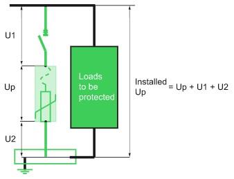
SPD has a voltage protection level Up that is intrinsic, i.e. defined and tested independently of its installation. In practice, for the choice of Up performance of a SPD, a safety margin must be taken to allow for the overvoltages inherent in the installation of the SPD (see Figure 3).
Fig. 3– Installed Up
The “installed” voltage protection level Up generally adopted to protect sensitive equipment in 230/400 V electrical installations is 2.5 kV (overvoltage category II, see Fig. 4).
Number of poles
Depending on the system earthing arrangement, it is necessary to provide for a SPD architecture ensuring protection in common mode (CM) and differential mode (DM).
Fig. 4 – Protection need according to the system earthing arrangement
TT
TN-C
TN-S
IT
Phase-to-neutral (DM)
Recommended
–
Recommended
Not useful
Phase-to-earth (PE or PEN) (CM)
Yes
Yes
Yes
Yes
Neutral-to-earth (PE) (CM)
Yes
–
Yes
Yes
Note:
1. Common-mode overvoltage
A basic form of protection is to install a SPD in common mode between phases and the PE (or PEN) conductor, whatever the type of system earthing arrangement used.
2. Differential-mode overvoltage
In the TT and TN-S systems, earthing of the neutral results in an asymmetry due to earth impedances which leads to the appearance of differential-mode voltages, even though the overvoltage induced by a lightning stroke is common-mode.
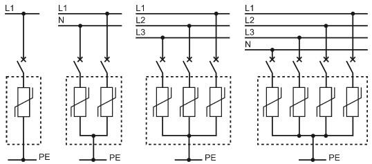
2P, 3P and 4P SPDs
(see Fig. 5)
1. These are adapted to the IT, TN-C, TN-C-S systems.
2. They provide protection merely against common-mode overvoltages.
Fig. 5– 1P, 2P, 3P, 4P SPDs
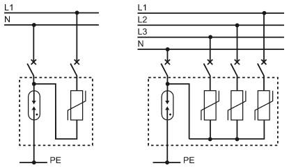
1P + N, 3P + N SPDs
(see Fig. 6)
1. These are adapted to the TT and TN-S systems.
2. They provide protection against common-mode and differential-mode overvoltages
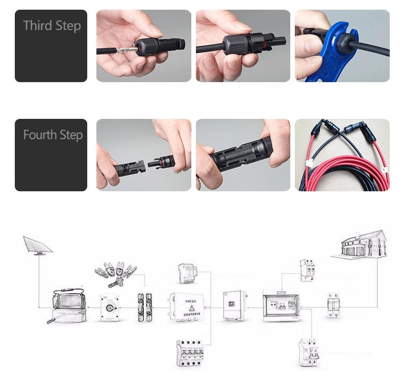
As the world moves towards renewable energy, solar energy has emerged as one of the most popular choices. The easy installation of solar connectors has made it easier to harness the power of the sun. In this article, we will explore the widespread use of solar connectors and how they are transforming the energy industry. […]
Connections of a SPD to the loads should be as short as possible in order to reduce the value of the voltage protection level (installed Up) on the terminals of the protected equipment. The total length of SPD connections to the network and the earth terminal block should not exceed 50 cm. One of the […]
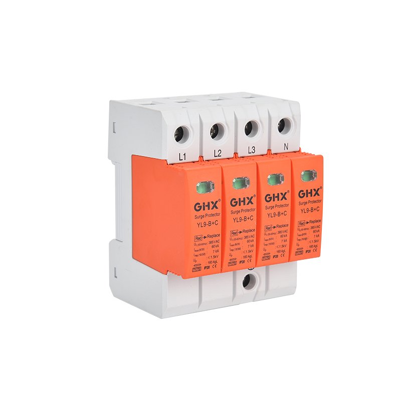
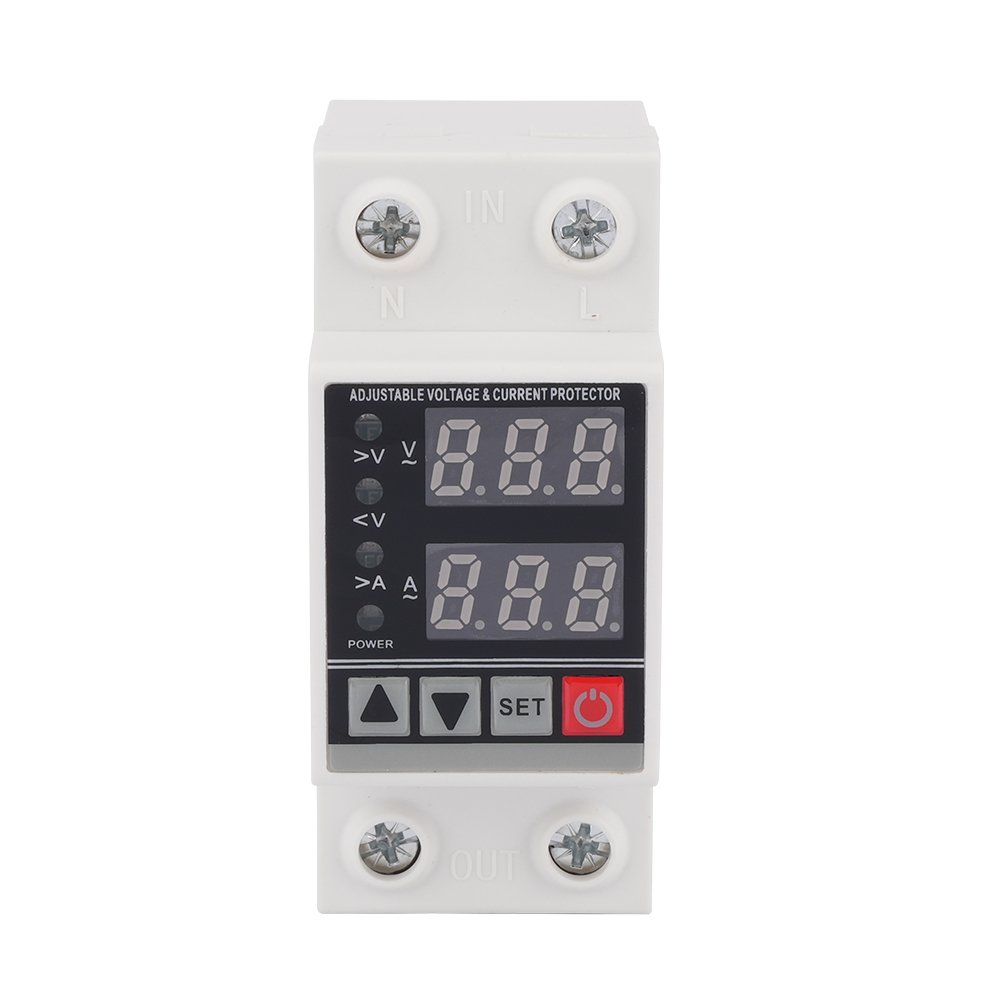
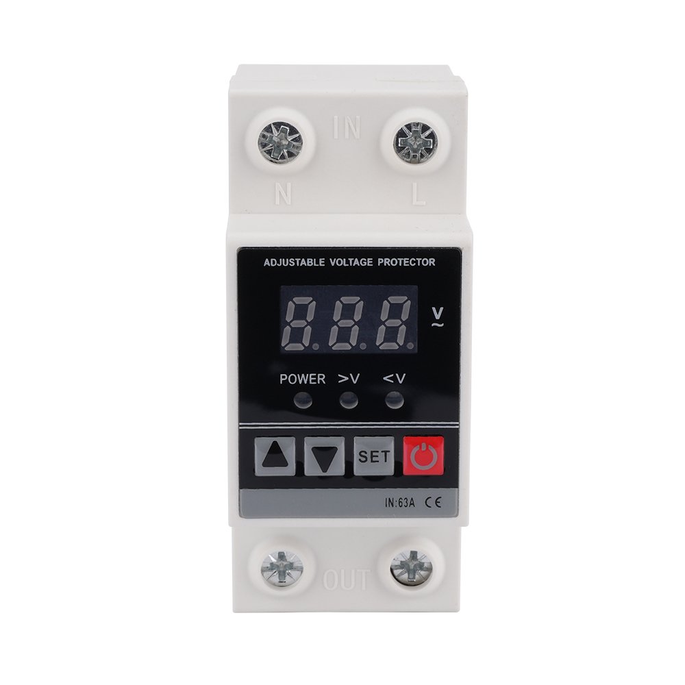
As we know, surge protective devices (SPDs) play a critical role in protecting electrical systems from power surges and spikes. When the visible windows is turned to be red, it means the surge protective devices (SPDs) are broken. What are the factors that cause surge protective device (SPD) to break? 1. Overvoltage Conditions Surge protective […]
We use cookies to enhance your browsing experience, serve personalised ads or content, and analyse our traffic. By clicking "Accept All", you consent to our use of cookies.