Common characteristics of SPDs according to the installation characteristics
Operating voltage Uc
Depending on the system earthing arrangement, the maximum continuous operating voltage Uc of SPD must be equal to or greater than the values shown in the table in Figure 1.
Fig.1 – Stipulated minimum value of Uc for SPDs depending on the system earthing arrangement (based on Table 534.2 of the IEC 60364-5-53 standard)
| SPDs connected between (as applicable) | System configuration of distribution network | ||
| TN system | TT system | IT system | |
| Line conductor and neutral conductor | 1.1 U / √3 | 1.1 U / √3 | 1.1 U / √3 |
| Line conductor and PE conductor | 1.1 U / √3 | 1.1 U / √3 | 1.1 U |
| Line conductor and PEN conductor | 1.1 U / √3 | N/A | N/A |
| Neutral conductor and PE conductor | U / √3 | U / √3 | 1.1 U / √3 |
Attn: N/A: not applicable
U: line-to-line voltage of the low-voltage system
The most common values of Uc chosen according to the system earthing arrangement.
TT, TN: 260, 320, 340, 350 V
IT: 440, 460 V
Voltage protection level Up (at In)
The IEC 60364-4-44 standard helps with the choice of the protection level Up for the SPD in function of the loads to be protected. The table of Figure 2 indicates the impulse withstand capability of each kind of equipment.
Fig. 2 – Required rated impulse voltage of equipment Uw (table 443.2 of IEC 60364-4-44)
| Nominal voltage of the installation (V) | Voltage line to neutral derived from nominal voltages a.c. or d.c. up to and including (V) | Required rated impulse withstand voltage of equipment (kV) | |||
| Overvoltage category IV (equipment with very high rated impulse voltage) | Overvoltage category III (equipment with high rated impulse voltage) | Overvoltage category II (equipment with normal rated impulse voltage) | Overvoltage category I (equipment with reduced rated impulse voltage) | ||
| For example, energy meter, telecontrol systems | For example, distribution boards, switches socket-outlets | For example, distribution domestic appliances, tools | For example, sensitive electronic equipment | ||
| 120/208 | 150 | 4 | 2.5 | 1.5 | 0.8 |
| 230/400 | 300 | 6 | 4 | 2.5 | 1.5 |
| 277/480 | |||||
| 400/690 | 600 | 8 | 6 | 4 | 2.5 |
| 1000 | 1000 | 12 | 8 | 6 | 4 |
| 1500 d.c. | 1500 d.c. | 8 | 6 | ||
SPD has a voltage protection level Up that is intrinsic, i.e. defined and tested independently of its installation. In practice, for the choice of Up performance of a SPD, a safety margin must be taken to allow for the overvoltages inherent in the installation of the SPD (see Figure 3).
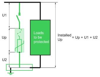
Fig. 3– Installed Up
The “installed” voltage protection level Up generally adopted to protect sensitive equipment in 230/400 V electrical installations is 2.5 kV (overvoltage category II, see Fig. 4).
Number of poles
Depending on the system earthing arrangement, it is necessary to provide for a SPD architecture ensuring protection in common mode (CM) and differential mode (DM).
Fig. 4 – Protection need according to the system earthing arrangement
| TT | TN-C | TN-S | IT | |
| Phase-to-neutral (DM) | Recommended | – | Recommended | Not useful |
| Phase-to-earth (PE or PEN) (CM) | Yes | Yes | Yes | Yes |
| Neutral-to-earth (PE) (CM) | Yes | – | Yes | Yes |
Note:
1. Common-mode overvoltage
A basic form of protection is to install a SPD in common mode between phases and the PE (or PEN) conductor, whatever the type of system earthing arrangement used.
2. Differential-mode overvoltage
In the TT and TN-S systems, earthing of the neutral results in an asymmetry due to earth impedances which leads to the appearance of differential-mode voltages, even though the overvoltage induced by a lightning stroke is common-mode.
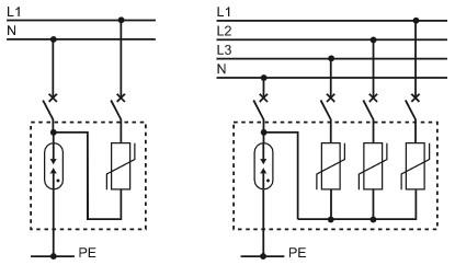
2P, 3P and 4P SPDs
(see Fig. 5)
1. These are adapted to the IT, TN-C, TN-C-S systems.
2. They provide protection merely against common-mode overvoltages.
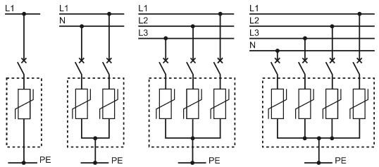
Fig. 5– 1P, 2P, 3P, 4P SPDs
1P + N, 3P + N SPDs
(see Fig. 6)
1. These are adapted to the TT and TN-S systems.
2. They provide protection against common-mode and differential-mode overvoltages